CorelDRAW is the most popular vector design software in the professional computer-aided fashion design industry, with many fashion designers using it to draw their mannequins and produce their designs. If you have attended fashion school or have simply visited a fashion design studio, you have likely seen the small wooden mannequins perched on the drafting tables. This classic mannequin is often used as a visual aid when creating different fashion figurine poses. You may not have one of your own, in which case you will find it very useful to have one in digital format and use it as a guide for creating the different poses of your upcoming designs.
This tutorial or creative exercise will let you create a geometric jointed mannequin using the CorelDRAW basic shape drawing tools ( Ellipse, Polygon and Rectangle) along with the Weld and Trim shaping options.
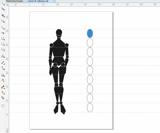
If you don't have previous experience drawing fashion figurines, before drawing the geometric shapes that will form yours we recommend that you start by positioning guidelines according to the proportion ratio that you decide on. The divine proportion or golden ratio is a guideline that establishes the ideal proportions of the human body, dividing it in sections called modules. Artists and scientists throughout history have established several ratios appropriate of their era and the figurative concepts of their times. When designing fashion figurines, the Greek golden ratio with some variations is often used. According to this ratio the size of the head is used as reference to define the subdivisions, so that the total height of the body is 8 times the size of the head. Since the fashion figurine needs to be more stylized for a slimmer and more elegant shape, the Greek ratio is slightly modified for a height of 9 or 10 times the size of the head.
If you find it helpful to have guide lines on your screen for better positioning of your geometric shapes, click and drag as many lines as you need from the horizontal or vertical rulers. These lines will not be visible when printing.
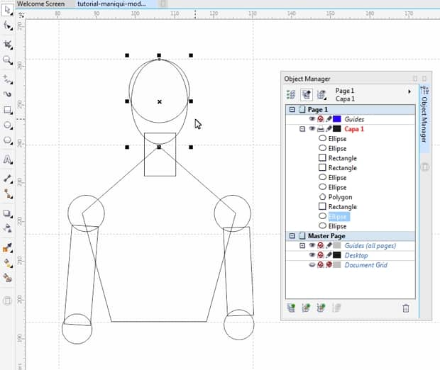
We will start drawing the head and neck using two ellipses and a rectangle (using the Ellipse and Rectangle tools from the Toolbox). Using the Polygon tool we will create a pentagon (5-side polygon) for the torso, and with the Ellipse tool we'll create two circles for the shoulders. To complete the upper part of the body, we will draw two rectangles and then, using the Pick tool, we will turn them a few degrees to find the right inclination. We'll then create two circles to function as elbows, as shown in the following image.
To create the pelvis we will use a pentagon that we will stretch using the Pick tool and two circles in its base that will serve as joints for the legs.
To draw the forearm we shall use a pentagon and a triangle. The hand will be made of another downward-facing pentagon joined to the forearm by a circle, as illustrated below.
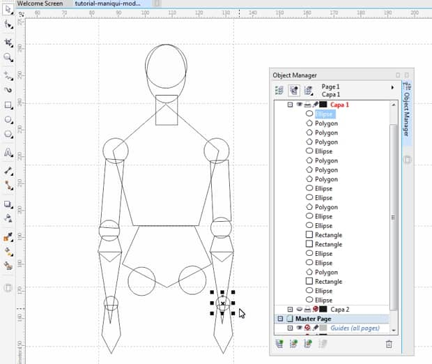
To draw the leg and foot we will use four pentagons and two triangles, and two circles for the knee and ankle respectively.
Once we have created one leg, we can duplicate it and place the two side-by-side. Using the Pick tool we can rotate some of the components in order to get asymmetry and movement.
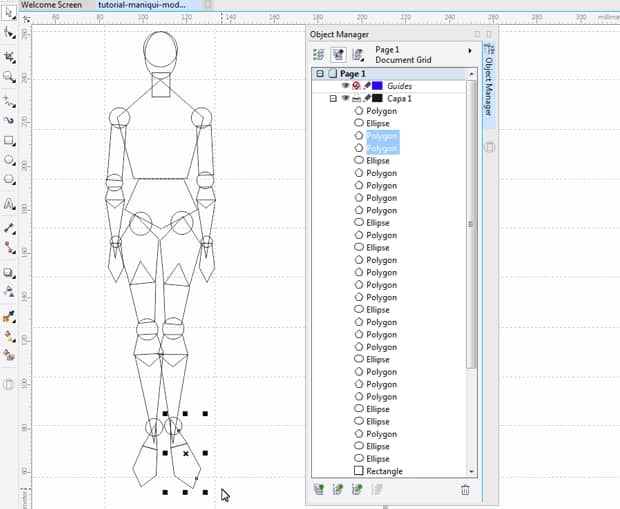
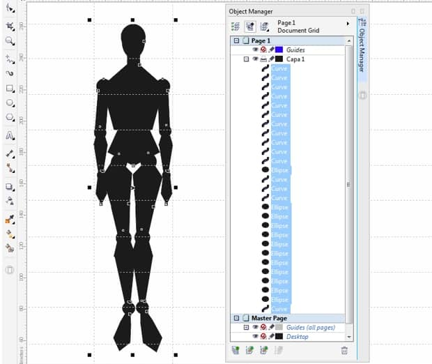
At this point, the mannequin already has all of its elements, comprised exactly of 37 basic objects. We can view them in the Object manager docker. To open the Object manager click on the Window menu > Dockers > Object Manager.
Once the mannequin has all of its components, we can optimize it using the shaping tools mentioned earlier. More specifically, we will use the Weld and Trim options.
To simplify the future use of the mannequin we will reduce the number of components by welding some of them together.
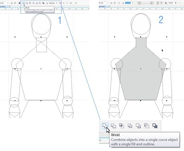
We will start by joining the torso to the neck. Select both shapes (the pentagon and the rectangle) and click on the Weld button on the Property Bar , and you will see how both shapes become a single object.
Weld also the two ellipses that form the head into a single object.
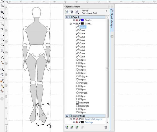
We will then select the two polygons that form the forearm and will Weld them together. To help visualize the results, it is a good idea to select the resulting objects using the Pick tool and apply a fill color to them by clicking on the color of your preference from the color palette. We will continue welding the polygons that form the thighs, the calfs and the feet until we get a result similar to the following image.
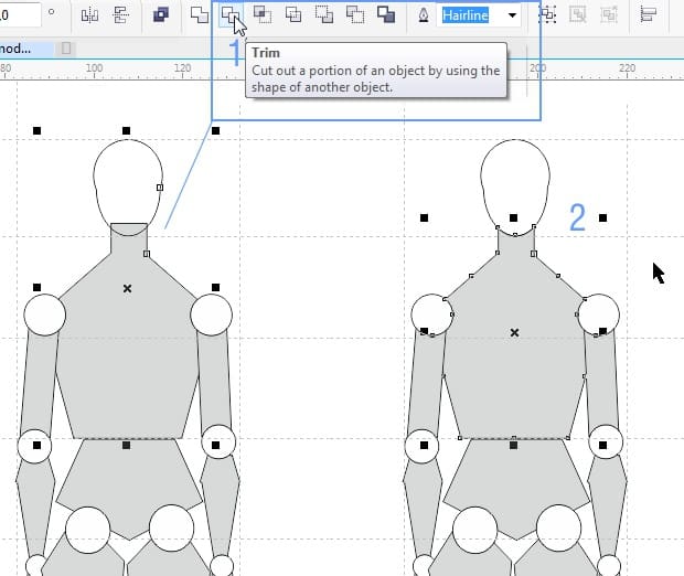
The number of components of the original figurine has now been reduced to 27. In order to provide mobility to the joints we will trim the areas where the objects come together using the Trim option from the Property Bar . We can start by selecting the ellipse that forms the shoulder, clicking the Trim option and then clicking the pentagon that forms the torso. Since the triangle that forms the forearm extends to the hand, we will need to select the pentagon that forms the hand, activate the Trim option and click on the forearm triangle. This way, the hand and forearm will be ready for when we trim the wrist.
Continue trimming all the ellipses that make up the joints of the adjacent objects. If the object that forms the head appears behind the neck, click on the Object menu > Order > In Front Of... and add a white fill color to distinguish it better. To create the ankles we will follow the same procedure as with the wrists: select the object that represents the foot, activate the Trim option and click on the calf object, then trim the ellipse corresponding to the ankle.
Now that the mannequin is ready you can delete the lines that you used as guides, by choosing the Pick tool, clicking on each one of them and pressing the Delete key.
To unify the appearance of the figurine, select all the objects that comprise it with the Pick tool and click on the black color of the color palette.
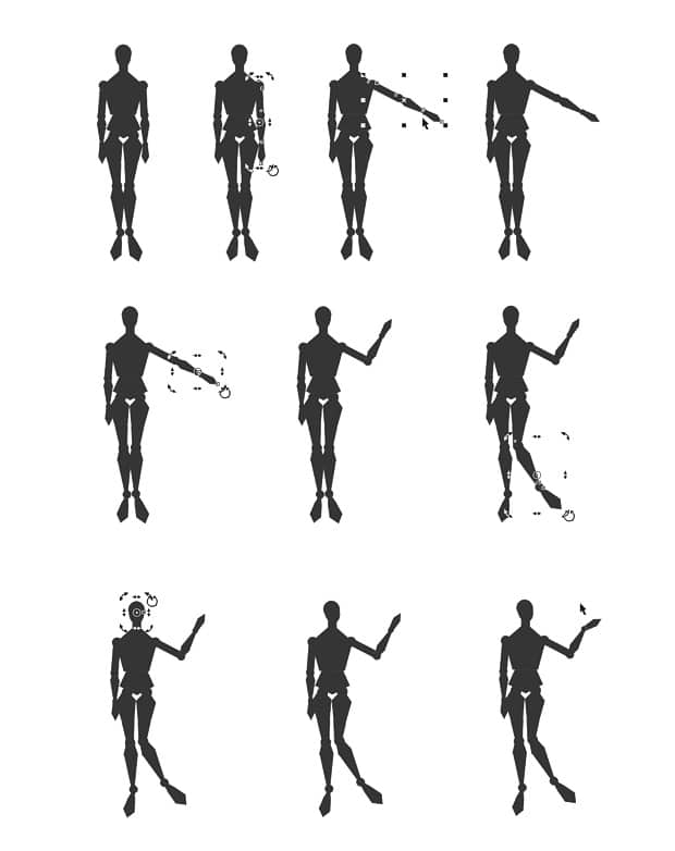
Now we can test the versatility of the mannequin that we've just created.
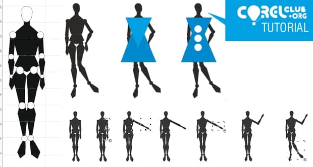
Using the Pick tool and its skewing and rotating functions you can select the joints and give your new mannequin movement, and position it in as many poses as your want. The possibilities are endless, as shown in the below example.
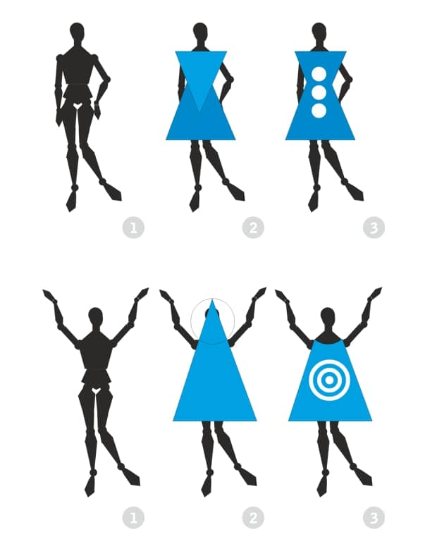
You have seen the possibilities of the basic shape drawing tools to create mannequins, but there is much more creative power in these tools. Now that you have your geometric mannequin as a starting point, try dressing it up using the techniques for drawing basic shapes, trimming and welding as shown below:
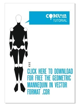
If you don't have the time to follow this tutorial from the beginning, feel free to download the completed geometric mannequin and start by dressing it or moving it around to find new poses. Click on the following image to download the vector file in .CDR format. You will be able to open directly in CorelDRAW.
This tutorial has been produced by Anna María López López - multidisciplinary designer, founder of www.corelclub.org and author of numerous design and fashion books such as Figurines de Moda, Técnicas y Estilos (www.figurinesdemoda.com) and Coolhunting Digital, a la caza de las últimas tendencias (www.coolhunting.pro).
Source: http://www.corelclub.org/tutorial-maniqui-de-moda-geometrico-en-coreldraw/